Nexus 4 E960 Repair Guide
June 4, 2018 | 0 Comments
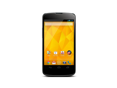
This take apart repair guide shows how to disassemble the LG Google Nexus 4 E960 quickly and safely. This guide was designed by the Repairs Universe team and can help you replace a cracked or damaged touch screen glass digitizer, and damaged or faulty LCD display screens, as well as other internal faulty parts such as speakers, battery, and buttons.
Nexus 4 Repair Resources
This Step by Step Video demonstrates how to replace the glass back cover on a LG Google Nexus 4 E960.
Recommended Tools:
Nexus 4 E960 Back Glass Cover Replacement Video
LG Nexus 4 E960 Teardown Repair Guide
This guide will help you to install the following LG Nexus 4 E960 parts:
Recommended Tools:
- Small Phillips Screwdriver
- T5 Torx Screwdriver
- Small Flathead Screwdriver
- Adhesive Strips
- Safe open Pry opening Tool
LG Nexus 4 E960 Take Apart Repair Guide:
- The first step in taking this device apart is to take out the SIM card and tray
- Next using a T5 torx screwdriver remove 2 screws located at the bottom of the device near the charging port
- After you have removed the 2 screws you will need to begin releasing the clips and remove the back cover.
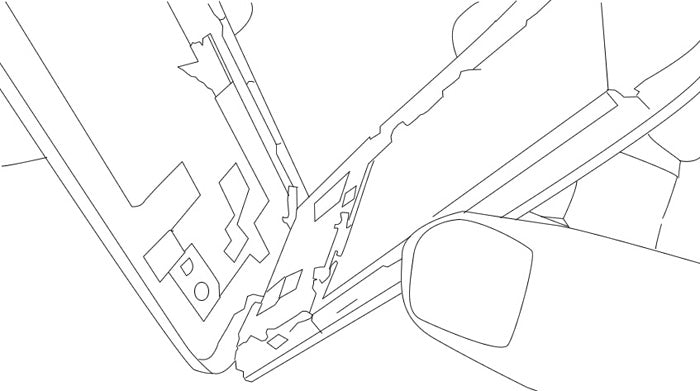
- Using a safe open pry tool, you will need to release 8 clips which are divided evenly around the outside edges (4 on the long sides and 2 on the shorter sides)
- Now you have access to the battery. Remove the 2 small Phillips screws holding the battery in, located near the under the camera and flash
- Use the safe open pry tool gently lift up and release the battery flex cable
- Disconnect the white antenna cable next to the battery and move it out of the way of the battery
- You will need to apply heat using a hot hair dryer or heat gun to the battery for about 20 seconds around the edges of the battery. This will loosen the adhesive holding it firmly in place.
- Next using a small Phillips screwdriver, you will need to remove 9 screws around the outside of back cover
- Once the screws have been removed you can then release 3 clips holding the back cover in and remove. There are 3 clips total, one by the loud speaker and two on each side by the screw holes as shown here
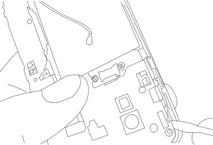
- Next step is to remove the loud speaker housing. Remove 2 small Phillips screws holding this housing in place in order to remove the housing
- Now you can disconnect and remove the antenna cable
- You can now remove the Micro USB charging port connector by releasing its pop connector and gently peel away this flex ribbon which is held in by a bit of adhesive
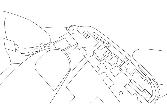
- Using a safe open pry tool lift up and release the LCD and touch screen digitizer pop connectors which will allow you to remove the camera
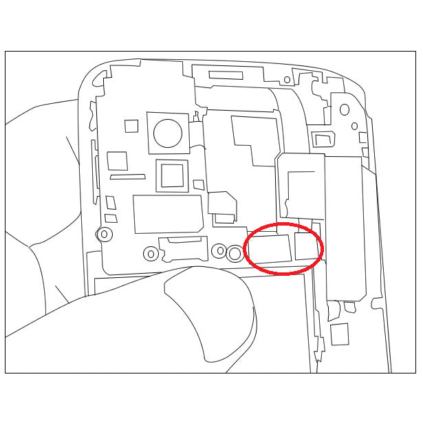
- Release the cameras pop connector. You can simply pull the camera out once this has been done
- Do the same for the headphone jack at the top of the device. You can wiggle and remove the headphone jack which is held in by a bit of adhesive as well.
- Now that all connections and components have been released/removed from the main board you can push in the SIM card tray release and the main board will lift away with ease if it does not then make sure all connections have been released on the board
- The final step is to remove the green volume button and power button flex cables and once this is done you are ready to replace the screen assembly
Notice/Warning:
RepairsUniverse does not accept any liability for damage, or injury caused, while you are following our disassemble guides. We make no representations, warranties, or conditions of any kind, express or implied. Utilizing these guides to assist you in repairing your mobile devices will void your warranty. RepairsUniverse strictly prohibits altering or modifying our teardown guides for commercial use, reproduction, or publication
