Motorola Photon Q Screen Replacement Repair Guide
June 4, 2018 | 0 Comments
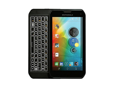
This Motorola Photon Q 4G Repair Guide will teach yopu how to take apart the Photon Q 4G LTE XT897 for a repair. If you need to install a new screen replacement, or other internal part use this step-by-step tutorial to assit you in replacing a broken glass touch screen, faulty LCD or other component that may have stopped working or become damaged. We have created a set of detailed images to better assist in each step of the tear down process to help you get your Photon Q 4G looking and working like new again with brand new parts.
This repair guide will assist in the installation of the following Motorola Photon Q 4G LTE XT897 parts:
- Motorola Photon Q 4G LTE XT897 Touch Screen Replacement
- Motorola Photon Q 4G LTE XT897 LCD Screen Replacement
Need a part not listed above? See our complete selection of Motorola Photon Q 4G Replacement Parts.
Recommended Tools:
Motorola Photon Q 4G LTE XT897 Take Apart Guide:
How to Repair your Motorola Photon Q 4G LTE XT897 (Instructional Guide) :
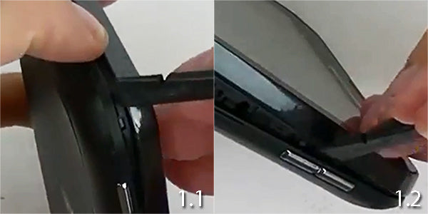
- (Figures 1.1 & 1.2) Take your Spudger tool and start from the bottom. Wedge the pry tool in-between the back cover and the housing.
- Once you have it open you can go around the cover and release the clips holding the cover on.
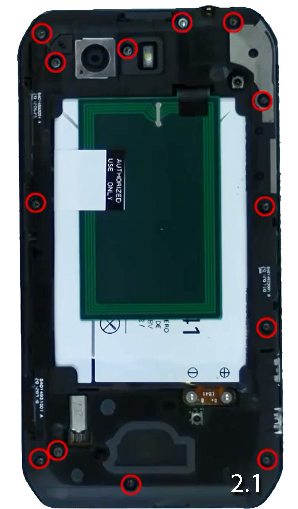
- (Figure 2.1) Remove the thirteen (13) T4 Screws circled in RED in the figure below. They are all the same size, just different color.
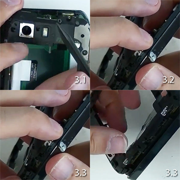
- (Figures 3.1 & 3.2) Shows you have to take the back housing off with your Spudger tool. Start from the top close to the camera. ( Go slow and make sure you don`t release the camera flex or pull it from the motherboard.
- (Figures 3.3 & 3.3) Once you have it started on the top you can work down on the sides and bottom of taken the back housing off. ( Again, go slow here. There is no need to rush as you do not want to damage any components. )
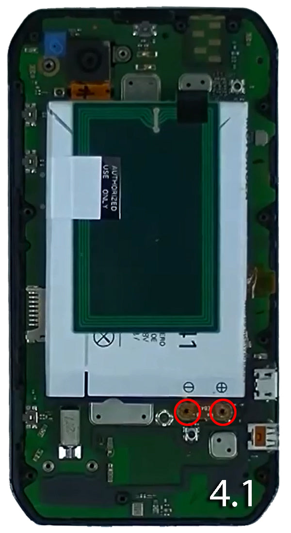
- (Figure 4.1) Here we see two (2) T4 Screws holding the battery in place. Theses are different than the 14 screws we removed off earlier. So should separate them from the first pile of screws you removed.
- These screws will be holding the battery in place.
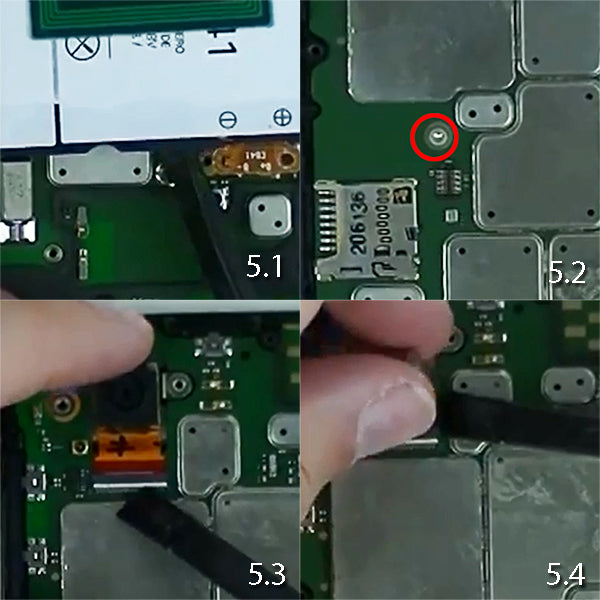
- (Figure 5.1) Shows you how to remove the Battery after you have removed the screws. Take your Spudger tool and begin prying from the bottom to the left side of the screws you took out earlier.
- (Figure 5.2) Shows one (1) T4 screw that is holding down the motherboard to the housing. This screw will be different then the rest as well. Remove it and place it separately from your pile for re-assembly.
- (Figures 5.3 & 5.4) Pop up the jaw-bone connector holder that is holding down the camera flex. This is the small white tab that will need to be put in the up-right position. Once it is up, grab your flex cable of the camera and slide it out. Go slow as you do not want to rip this cable.
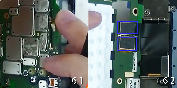
- (Figure 6.1) Grab your motherboard from the right side with your Spudger tool and slowly open it like a book. Do not rush here. On the other side of the motherboard you will see two flex cables. See Figure Below For Reference.
- (Figure 6.2) You now see two (2) Flex Cable Connections. Take your Spudger tool and unlink those from the motherboard. Place your motherboard off to the side. Be sure to handle with extreme care.
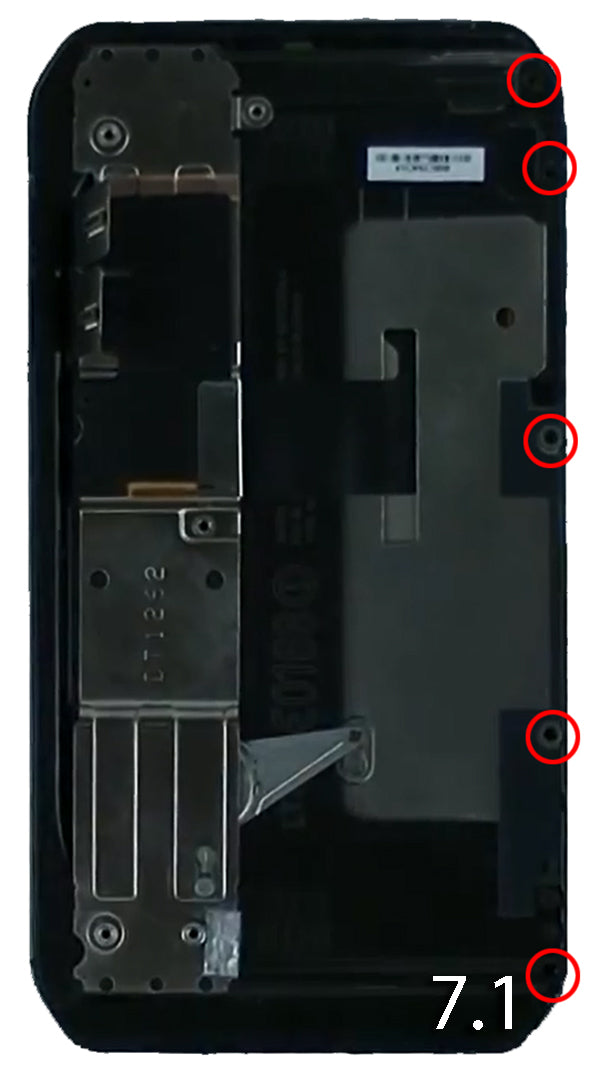
- (Figure 7.1) You now see five (5) T3 Screws. Remove these screws and place them away from your pile. Theses screws are different and should be labeled separately from your screw piles for re-assembly. This plate holds the flex cable to allow the slide on your phone.
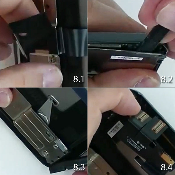
- (Figure 8.1) Remove the flex cable that is on the slide. There will be a tiny metal plate that holds the ribbon in place.
- (Figure 8.2) Shows you how to get started to remove the metal housing on the slide . Take your Spudger tool and start from the top right. Wedge the tool in side and slowly pry back . Once you have it open go down the right side and then towards the bottom.
- (Figure 8.3 & 8.4) Will show you how to remove the casing from the left side now. This may be be a little tricky as there are 4 holders that the Slide housing goes in. You will need to go with the holes here as you see below.
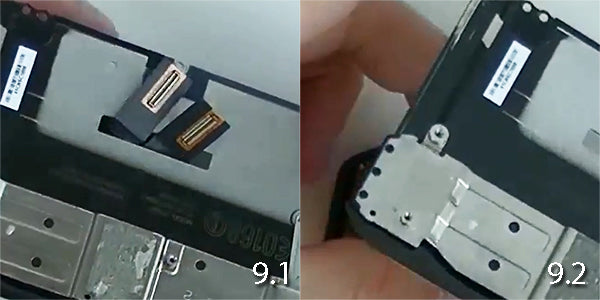
- (Figure 9.1 & 9.2) Once the sliding housing starts coming off, Slide the ribbon cable in the hole that is on the casing. This will release the sliding housing from the rest of the main housing.
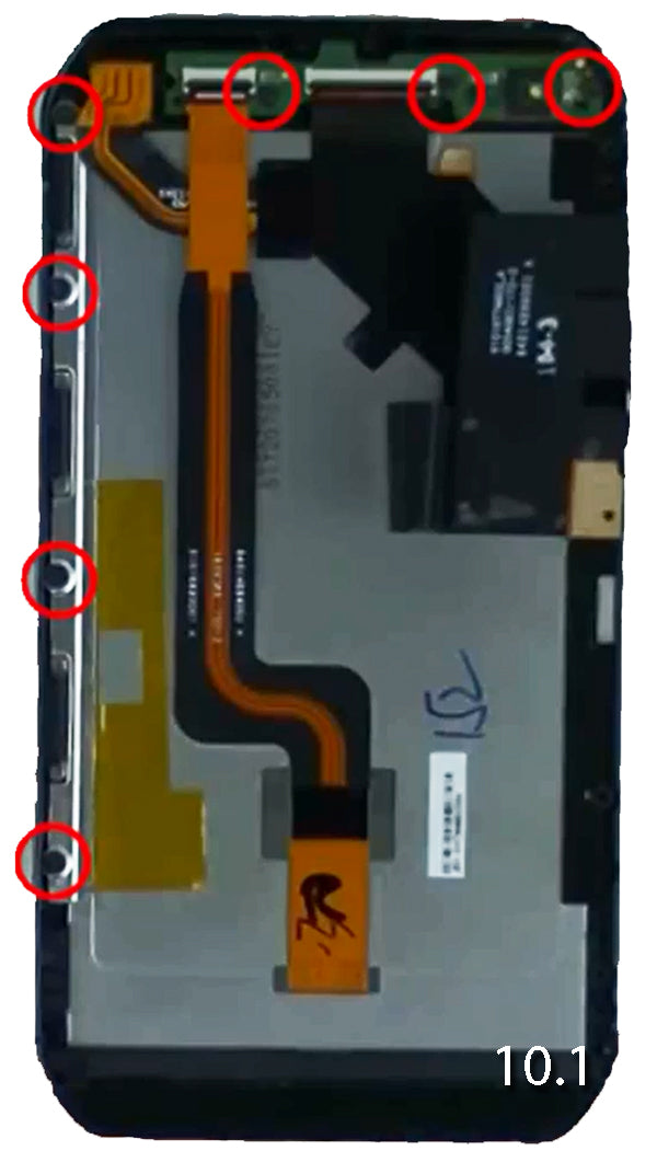
- (Figure 10.1) You now see seven (7) T3 Screws here. Remove these screws and place them in a different separate pile. They will be different size from the rest.
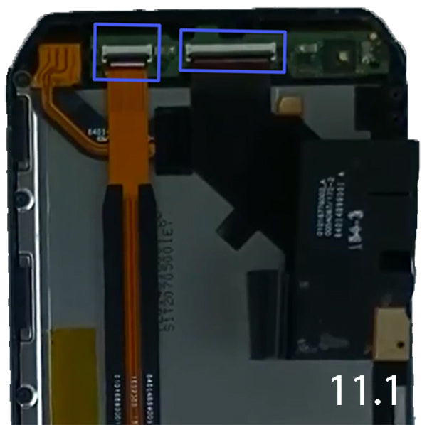
- (Figure 11.1) On the top motherboard you should see two (2) flex cables. Release them from the motherboard. ( Go slow as not to rip or break the cables.
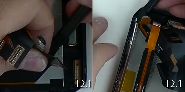
- (Figure 12.1) Shows you have to remove the (2) flex cables from above. DO NOT remove it from the LCD . Just unlink them from the jawbone flex holder.
- (Figure 12.2) On the left hand side of the phone you will see a small metal frame. He comes up . Take him off with your Spudger tool . Go slow as he does bounce up and could become lost after you pry him up.
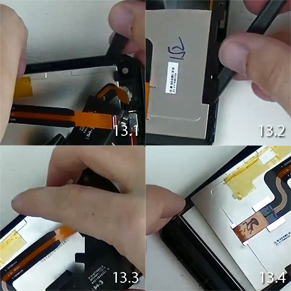
- (Figure 13.1) Will show you how to remove the LCD from the Glass Touch Screen Digitizer. Start from the left hand side towards the top. Wedge the Spudger tool in-between the LCD and the outer edge of the Touch Screen Digitizer.
- (Figure 13.2) Once you have the top started, work the right side and go to the bottom.
- (Figure 13.3 & 13.4) Once you have the sides take off. You will see that the LCD will start to come up from the top. Once you have enough of the adhesive released you should be able to separate the LCD for the Glass Digitizer.
You have now learned how to take apart the Motorola Photon Q 4G. If you need to purchase the parts to repair your broken or cracked LCD, Touch Screen Digitizer, or other internal part. Shop our selection on Motorola Photon Q 4G Parts.
Notice:
Repairs Universe's guides are for informational purposes only. Please click here for details.
Learn about restrictions on reproduction and re-use of Repairs Universe's repair/take-apart/installation guides, and about creating hyperlinks to our guides

