Dell Latitude 10 Screen Replacement Repair Guide
June 4, 2018 | 0 Comments
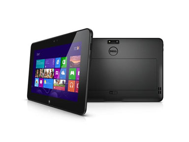
This is the Dell latitude screen repair guide brought to you by Repairs Universe. If the LCD, or glass Touch screen of your Dell Latitude is broken or damaged and you need to repair it, this instructional manual will lead you through the entire process. With this guide, you will learn how to tear apart your Dell Latitude 10 to perform a repair such as replacing a broken or cracked glass touch screen digitizer or any other faulty internal component. This repair guide will take you through systematically, describing how to appropriately and safely disassemble the Dell Latitude 10 and install a new screen replacement.
This repair guide will aid in the installation of the following Dell parts:
If the component you want to replace is not listed above, please see our complete selection of Dell Latitude 10 Replacement Parts.
Tools Required:
Dell Latitude 10 Take Apart Guide:
How to Fix your Dell Latitude 10 (Instructional Guide):
- Before opening the inner components of your device, ensure that you are working on a clean flat surface, and then completely turn the device off. You should also disconnect network cables as well as any attached accessories from the tablet. Remove also the SIM card and the external card from its slot.
Removing the battery and back housing from the back of the device.
- Flip over the tablet upside down. Start by opening the back cover, then lift the battery outwards using the pry tool and remove it from the device.
- (Figure 1.1 & 1.2) With the battery removed, we now have two small flat screws on each bottom corner of the battery slot. Remove each of the screws and put them in a secure place to avoid losing or misplacing them.
- Once the screws are removed, you will be able to release all the clips fastening the back housing to the rest of the device.
- (Figure 1.3) Start prying from the outside edge at the right side using the spudger tool or any other pry tool you want.
- (Figure 1.4) Next, slowly work your way around releasing each of the clips from their fixed positions. Remove from each side and at the bottom and then finish with the top, prying in the same way.
- With all the clips removed, you can then pull away and remove the back housing.
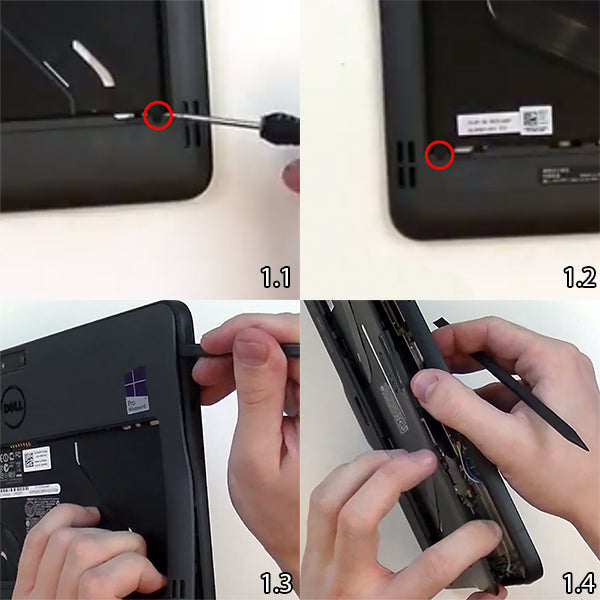
Figure 1
Removing motherboard connections to access the screen
- On removing the back housing, you will have the motherboard fully exposed. You will be able to release a few clips and screws in order to reach the screen.
- (Figure 2.1) At the bottom position of the device where we have the slider for the battery, you will see two small flat screws. Remove these screws.
- (Figure 2.2) Lift up the slider. There is a spring that assists its release from its position.
- Lift up and then push down the small clip in the centre and then you will be able to release the spring and remove the slider.
- (Figure 2.3) On the right side, you will see a screen connection that you will need to release back and then pull out the cable.
- (Figure 2.4) Directly above this position, there will be one more flex cable for you to release as indicated in the image below. You will leave the motherboard intact, as you do not need to remove it when replacing the screen.
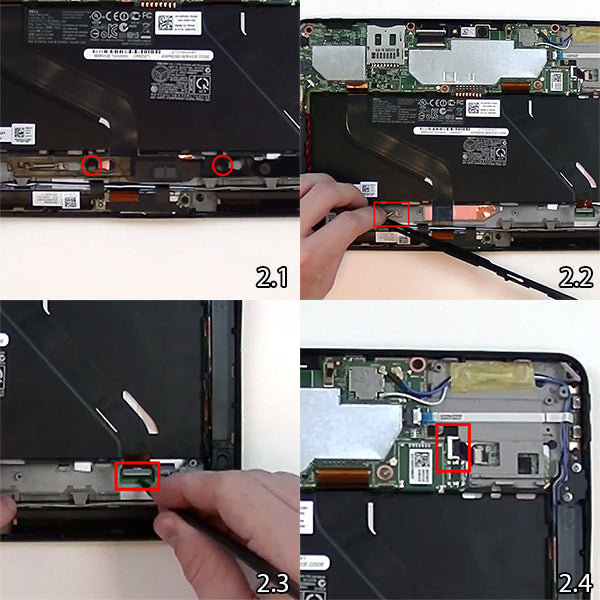
Figure 2
Separating the screen assembly from the front housing
- (Figure 3.1) Flip the device to the front side and begin warming the front end of the screen. Since you still have the motherboard intact, you need to use very low heat. Just take your time when heating the screen and be cautious.
- Note that if you use too much heat you run the risk of damaging the motherboard and its components. So just proceed with carefulness, ensuring that you use low to medium heat and not beyond there! Heat for about 30 to 45 seconds specially treating the outside edges of the screen.
- (Figure 3.2) Once the screen is adequately heated, you can begin releasing some of the adhesive holding the screen assembly to the frame.
- Carefully insert the spudger tool underneath and begin releasing the soft adhesive from the right side as shown below. The adhesive loosens upon heating but becomes sticky on cooling so ensure you reheat occasionally and very slowly. Again, be careful with the heat to avoid damaging the flex cables or the motherboard itself.
- (Figure 3.3) As demonstrated in the image below, you wedge the spudger tool to release the adhesive on one side of the device and then spread the gap further downwards towards the bottom. Try to let loose as much adhesive as you can before reheating.
- (Figure 3.4) Continue working on the bottom side close to the home button as the adhesive loosens and gives way especially upon reheating slightly.
- (Figure 3.5) Beneath the home button, there will be a small piece of tape that supports a flex cable. Release the tape and then release the flex cable that is connected to the copper below it.
- (Figure 3.6) Once you are done with loosening the rest of the adhesive around the screen, you are just about done with opening your Dell Latitude 10. You have separated the screen assembly from the front housing with its attached motherboard.
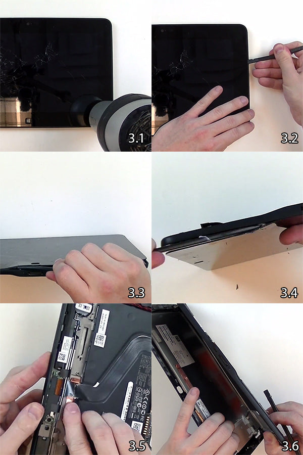
Figure 3
Detaching the back plating
- You are now remaining with one final step?that of removing the back plating for the LCD screen.
- (Figure 4.1) Use a spudger tool that can access the corners and insert it between the plating and the screen, underneath one corner of the back plating.
- (Figure 4.2) Gently lift the sheet from one top corner making use of the appropriate pry tool.
- (Figure 4.3) Insert the pry tool in a second corner and begin releasing some of the adhesive.
- (Figure 4.4) Using the strength of the two detached corners, you can now pull the sheet off from the screen.
- Remove the tape at the bottom and then you can completely remove the back plating and the adhesive, which you can reuse with the new LCD screen.
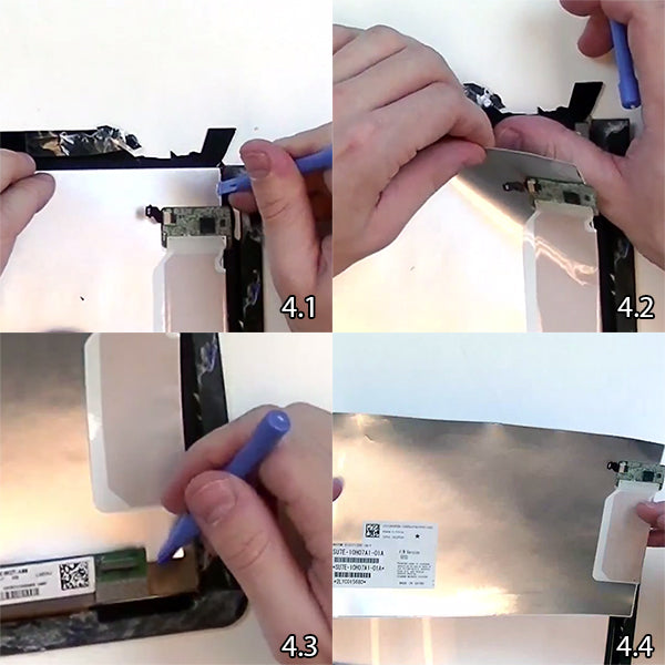
Figure 4
That is it! You have now taken apart your Dell Latitude 10 for a touch screen assembly or replacement without having to detach it from the motherboard. Your device is now ready for revamping with new components.
Notice:
Repairs Universe's guides are for informational purposes only. Please click here for details.
Learn about restrictions on reproduction and re-use of Repairs Universe's repair/take-apart/installation guides, and about creating hyperlinks to our guides.