HTC Touch Pro 2 Take Apart Repair Guide
June 4, 2018 | 0 Comments
View the downloadable version of our how to fix your HTC Touch Pro 2 screen guide.
This take apart repair guide shows how to disassemble the HTC Touch Pro 2 cell phone quickly and safely. This guide is designed by the Repairs Universe team and can help in the installation of replacement parts to repair a damaged cell phone.
This guide will help you to install the following HTC Touch Pro 2 part(s):
Tools Required:
- Safe Open Pry Tool
- Small Phillips Screwdriver
- T5 Torx Screwdriver
- Tweezers (optional)
HTC Touch Pro 2 Take apart guide:
- In order to disassemble HTC Touch Pro 2, first of all you will need to take the stylus out of its enclosure and then remove the back cover (battery cover) of the phone. Also remove the battery from the phone.
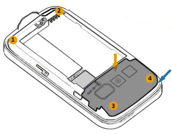
Figure 1
- You will now need to unscrew four T5 screws from the back of the phone. Using a T5 Torx screwdriver, remove these screws at the locations shown in figure 1.
- Using safe open pry tool, carefully lift up the rear top cover / antenna module (highlighted using dark gray color in figure 1) from the side indicated by blue arrow. But note that you will need to remove a cable connector from underneath (indicated by orange arrow in figure 1) before you can be able to completely separate the antenna module from the unit. Release the connector using safe open pry tool when you have lifted the antenna module enough to access the connector. Now the antenna module will be separated.
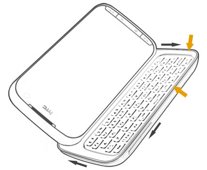
Figure 2
- Use the safe open pry tool again to pry off the rear housing from the unit. Insert safe open pry tool between the edge indicated in the figure by orange arrows. Carefully slide the tool along the sides, in the direction shown in the figure by gray arrows, to unclip the clips underneath. Note that in order to completely release the lower housing from the unit you will have to peel off the sticker from the SIM holder area.
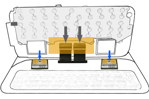
Figure 3
- Use safe open pry tool to separate the motherboard from the keyboard underneath and then flip open the motherboard from the side as shown in the figure 3.
- Remove the tape that covers the two connectors on the motherboard at the location highlighted in figure 3.
- Disconnect both the connectors on the motherboard using the safe open pry tool. The locations of these connectors are indicated by gray arrows in figure 3. The motherboard will be free to remove now. Remove it from the unit and put it aside.
- You will now need to unscrew four screws at the locations highlighted in figure 3 by small orange circles. Remove these screws using small Phillips screwdriver but first you will have to remove a sponge like material from the screws with the help of tweezers.
- After removing the screws remove two metal shields using tweezers from both hinges (at the locations from where you have just removed the Phillips screws). And then move both hinges up to make these tilt so that these can run through the gaps on the keyboard when the keyboard is lifted off. The blue arrows in figure 3 indicate the locations to move up the hinges.
- Before you can remove the keyboard you need to peel the FPC off the keyboard so that it can run through the gaps on the keyboard when it is removed.
- You can remove the keyboard now, running both hinges and the FPC though the gaps on the keyboard. Put the keyboard aside.
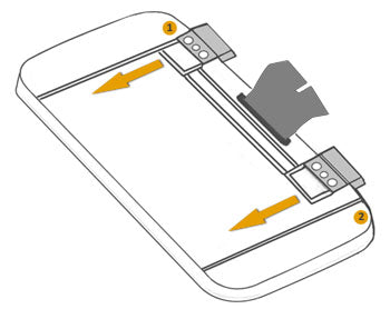
Figure 4
- Using a small Phillips screwdriver, unscrew two Phillips screws from the unit at the locations indicated in figure 4.
- Now you need to remove the back cover from the unit that includes the slider mechanism. Use a safe open pry tool to carefully unclip the clips holding this cover to the unit. Insert the tool between the edge (preferably start from the gap created by ?Power? button) and then slide the tool along the sides in the clockwise direction, to unclip the clips. Note that you will need to slide in the remaining assembly (indicated by orange arrows in figure 4) in order to pry up that side of the cover. Also note that once you have run the pry tool along the sides, you need to separate the tape between the main FPC and the cover before you remove the cover from the unit.
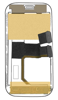
Figure 5
- Remove the tape and a fabric-covering from the locations highlighted in the figure 5.
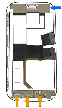
Figure 6
- Disconnect three connectors at the locations shown in the figure 6 by orange arrows. Use safe open pry tool to detach these cable connectors.
- Use safe open pry tool to lift up the receiver from the phone assembly. Note that the receiver is attached to the main FPC. A blue arrow indicates the position of the receiver in Figure 6.
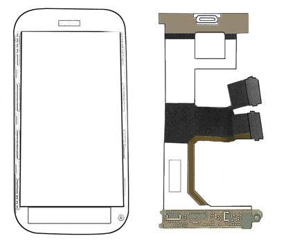
Figure 7
- You can now remove the main FPC from the back of the unit. The removed FPC is shown in figure 7.
The HTC Touch Pro 2 is now disassembled and you can replace the damaged part(s) with new ones. Reverse the instructions above to reassemble your phone.
Notice:
These replacement instructions are for informational purposes only. These are published on the http://www.repairsuniverse.com web site free of charge and without any kind of warranty. We will not accept any liability for damage or injury caused whilst following this guide.
The figures / diagrams are meant for guiding users about the locations of different parts of the device but these are not drawn to scale.
Reproduction:
We strictly prohibit any alteration or modification of the format or presentation of this guide for inclusion within other web sites and publications or otherwise. If you would like to make this guide available to other people, please do so by way of a hyperlink. You may print a copy of this guide for distribution, only if the entire layout is included and without any modification.