Sony Xperia Z Repair Guide
June 4, 2018 | 0 Comments
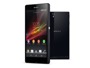
The Repairs Universe team put together this repair guide for the Sony Xperia Z so that you can tear down this device yourself and perform repairs like replacing a broken glass digitizer or cracked LCD screen. Reviewing this video guide and following along with the written guide will assist you in safely disassembling your device.
This repair guide will help when needing to install the following Sony Xperia Z parts:
Required Tools:
- Small Phillips Screwdriver
- Suction Cup Tool
- Adhesive Strips
- Safe Open Pry Tool
- Spudger Opening Tool
- Heat Gun or Blow dryer
How to Fix a Sony Xperia Z (Step-by-Step Tutorial) :
Sony Xperia Z Written Take Apart & Repair Guide
- Before starting the repair, make sure your device is completely powered off.
- Take a heat gun (on low heat settings) or a hair dryer (on medium heat settings) and heat along the edges of the device, holding your heating tool an inch or two from the edges. Do this for 30 to 45 seconds to loosen the adhesive that binds the back cover to the device without overheating it.
- Next, use your pry tool to wedge between the seams of the back housing and the device. This is made easier with the use of a suction cup tool. Stick the suction cup to the back of the back cover and tug on the ring, which will allow you to get between the seams with the pry tool more easily. If you do not have a suction cup tool, take your time and find a point of entry on the top of the device with the pry tool. Continue to run the pry tool along the seams of the sides until the device and back cover separate.
Figure 1
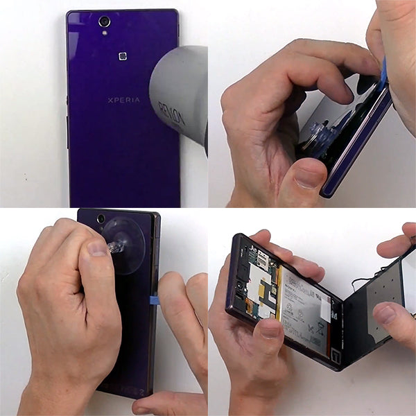
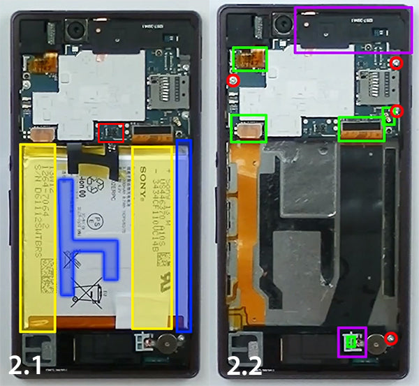
- Once the back cover is removed, the first thing you will want to do is release the battery connection and then take out the battery itself. Pry beneath the battery with the spudger tool to remove it, but be careful, as there is strong adhesive and two (2) flex cables holding it in place. Start on right side of the battery. Once the adhesive is released on the right side, begin prying underneath the lower center of the battery until you are able to carefuly take the battery out.
- Next, there are four (4) flex cables you will need to release (highlited in green below) as well as a small plastic spacer (highlighted in purple toward tthe bottom of the device) that you will take out. Once the spacer is removed, set it off to the side and use the pointy end of the spudger tool to release the vibrate motor pop connection that is located beneath where the spacer was.
- You can now use the dull end of the spudger or the pry tool to release the flex cable connectors and the small antenna attached to the motherboard. These connections are highlighted in green below.
- Next, unscrew and remove the four (4) Smal Phillips Screws highlighted in red.
See figure below for reference.
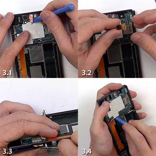
- Once the screws are out, there will be a smal piece of housing in the right top corner to remove. Once this is removed, it will expose a couple more connection that need to be released. The first is the main camera, whose connector is located beneath some copper tape that you can remove first (Figure 3.1). Take out the main camera and put it to the side. Then release the front camera connector.
- Use tweezers to remove the sim card tray on the side of the device, as shown in Figure 3.3. You will first need to remove the small covering over it.
- We can now remove the motherboard itself. Be cautious of the side cable flex and headphone jack connections to the motherboard.
See figure below for reference.
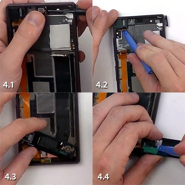
- If you are replacing the ear speaker, located in the top center (Figure 4.1), you will now use a Small Flathead Screwdriver to get underneath the adhesive and take the ear speaker out.
- The final component on the top is the haedhone jack and sensor cable, which is easily lifted with the pry tool.
- At the bottom, there is another segment of plastic housing that you will need to release using your pry tool (Figure 4.3). Start by prying beneath the left side, and be careful when lifting it, as there is an antenna that will still be connected to it on the right side. To separate thsi antenna, it is easiest to release the clips on the circuit board, as shown in Figure 4.4.
- This component contains your loud speaker and vibrate motor, in case you are replacing either of these parts.
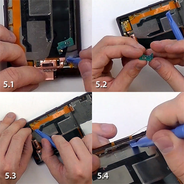
- Next, remove the final circuit board for the antenna in the lower right corner, as shown in Figure 5.1.
- Lastly, remove the side button flex cable + mic, as shown in Figure 5.3. Be careful as this flex cable is fragile. Once this flex cable is loosened, lift it up to expose the metal bracket beneath (Figure 5.4). Release the adhesive attaching the cable to the side buttons. This step is well demonstrated in the repair guide video. Once this flex cable is loosened, remove it and set if off to the side.
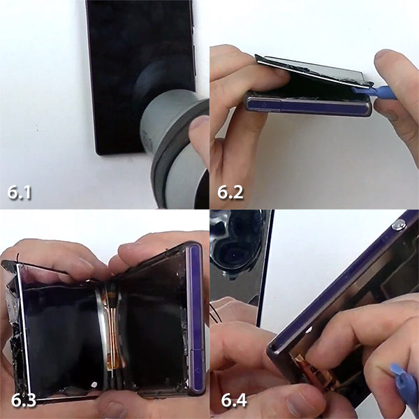
- You will now be able to begin heating the edges of the device in preparation for removing the screen. As before, heat the edges for 45 seconds to 1 minute at a time until you are able to use the pry tool to wedge underneath the screen. Since this adhesive is strong, it is not unusual for your old glass touch screen to break when you are wedging it out. You may want to start with the spudger tool to get better leverage upon entry. Reheat the edges if necessary
- After the screen has been removed, take off any remaining flex cables from the device, as in figure 6.4.
- To reassemble, simply reverse the order of the steps you just performed.
Notice:
Repairs Universe's guides are for informational purposes only. Please click here for details.
Learn about restrictions on reproduction and re-use of Repairs Universe's repair/take-apart/installation guides, and about creating hyperlinks to our guides