HTC Desire Take Apart Repair Guide
June 4, 2018 | 0 Comments
View the downloadable version of our how to fix your HTC Desire screen guide
Here the Repairs Universe team have put together a take apart repair guide showing how to disassemble the HTC Desire cell phone quickly and safely. This guide can assist with the installation of replacement parts.
This guide will help you to install the following HTC Desire part(s):
Tools Required:
HTC Desire Take apart guide:
- First of all remove the back cover of the phone using safe open pry tool. Remove the micro SD card and the battery from the phone as well.
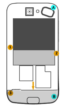
Figure 1
- Remove the two void stickers from the locations A and B highlighted with cyan color in figure 1.
- You will now need to unscrew three screws at the locations 1, 2 and 3 indicated in figure 1 by orange circles.
- Pry up the back-bottom cover using safe open pry tool. The cover is highlighted with gray color in the figure 1 and an orange arrow points to a convenient location to start prying with.
- You can now remove the back chassis which includes the battery compartment. To remove it you will need to pry it up using a safe open pry tool.
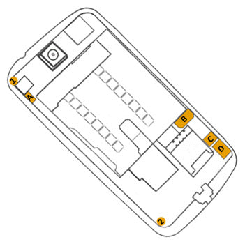
Figure 2
- Remove two more screws at the locations indicated in figure 2 by small circles 1 and 2.
- Disconnect the antenna plug from the location A indicated in the figure 2.
- Now carefully lift the camera PCB and remove the ?Power? button.
- You will now need to disconnect three cable connectors from locations B, C and D shown in figure 2. Carefully lift up the connectors using safe open pry tool to unplug.
- After unplugging the connectors you can now lift up and remove the camera PCB and primary PCB from the phone assembly. Remove it and put it aside.
- The next step is to remove the ?Volume? button from the unit.
- Once you have removed the ?Volume? button carefully loosen up the AMOLED and the keyboard assembly out of the chassis using safe open pry tool but do not remove these from the unit.
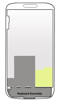
Figure 3
- Now lift up and remove the keyboard assembly. Note that you will have to peel off the part of keyboard assembly that is glued at the back of AMOLED. The location of keyboard assembly is shown in gray color in the figure 3.
- The removal of the keyboard assembly from the unit will expose the keyboard?s key-caps. Pry up and remove the key-caps as well.
- Peel the touch screen PCB assembly off the back of the AMOLED. Its location is highlighted by yellow colored area in figure 3.
- The AMOLED should now be free to remove. Remove it and put it aside.
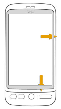
Figure 4
- Now in order to remove the touch screen digitizer from the phone chassis you will first need to peel off a sticky tape which connects the touch screen to the chassis. Then insert safe open pry tool in the edge between the chassis and digitizer from the back (as indicated by the arrows in figure 4), and pry up the digitizer. The digitizer will be adhered to the chassis and it will require a little bit of effort to separate the digitizer from the chassis. Note that once you have taken the digitizer out of the chassis you will need to remove the insulator from its flex cable and then run the flex cable from the gap in the chassis to separate it completely from the chassis (you may have to rotate the digitizer to let the flex cable run through the gap easily).
The HTC Desire is now disassembled and you can now replace the damaged part(s) with new ones. Reverse the instructions above to reassemble your phone.
Notice:
Repairs Universe's guides are for informational purposes only. Please click here for details.
Learn about restrictions on reproduction and re-use of Repairs Universe's repair/take-apart/installation guides, and about creating hyperlinks to our guides.